Introduction

Manufacturing engineers and procurement teams frequently face axis‑selection confusion when processing curved and sculptured components. Many buyers automatically choose 5‑axis milling for every curved feature without evaluating real‑world part requirements, leading to inflated production costs and unnecessary CAM programming overhead. Blindly adopting 5‑axis for moderately curved geometry often wastes budget without delivering tangible performance gains. Prismatic and mildly curved workpieces can achieve acceptable quality with mature 3‑axis milling workflows, as long as fixture schemes and toolpath strategies are well‑optimized.
Complex curved components from aerospace, medical implant, and mold‑making industries contain undercuts, compound angles and deep sculpted cavities that challenge conventional milling workflows. Each re‑clamping operation in multi‑setup 3‑axis production introduces stack‑up positioning deviation that damages final dimensional consistency of curved surfaces. Geometry complexity, tolerance targets and total manufacturing cost should jointly guide axis selection instead of machine technical specifications alone. Understanding the practical boundaries between 3‑axis and 5‑axis milling helps shops balance quality, lead‑time and project expenditure.
What core mechanical differences separate 3‑axis and 5‑axis milling?
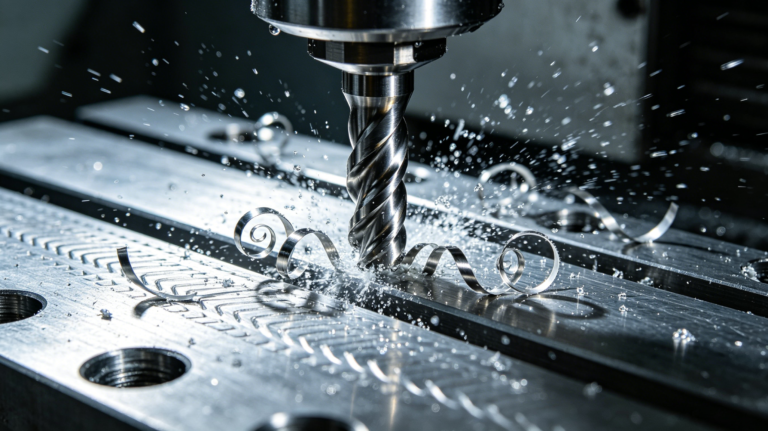
3‑axis milling operates only along X, Y and Z linear axes, keeping workpiece orientation fixed throughout the whole machining cycle, while 5‑axis milling adds two rotary axes enabling tilt and rotation for either cutting spindle or work tableCNC milling, which delivers multi‑angle tool access toward curved workpiece surfaces without repeated fixture adjustment. 3‑axis solutions rely on multiple manual re‑clamping to reach angled or hidden curved features, and every new setup accumulates small positioning errors on free‑form profiles. 5‑axis milling includes two practical variants: indexed 3+2 positioning milling and full simultaneous 5‑axis milling, and users must distinguish these two modes before quoting curved‑part orders. Rotary‑axis freedom fundamentally changes fixture dependency and achievable surface quality for complex curved geometry.
Linear‑axis limitation: 3‑axis machines cannot tilt cutting tools, so deep curved cavities demand long overhang cutters that trigger vibration and poor surface roughness.
Rotary‑axis flexibility: 5‑axis equipment adjusts tool inclination dynamically, applying short rigid cutters against curved profiles to suppress chatter marks.
Indexed 3+2 milling mode: Rotary axes lock after angular indexing, executing 3‑axis toolpaths; it suits multi‑angled curved features but not continuously‑changing sculptured surfaces.
Simultaneous 5‑axis milling mode: All five axes move synchronously, exclusively required for organic continuous free‑form curved surfaces such as turbine blades.
💡 Mechanical axis differences directly define which curved‑part features each milling technology can realistically accomplish.
When can complex curved parts still be manufactured by 3‑axis milling?
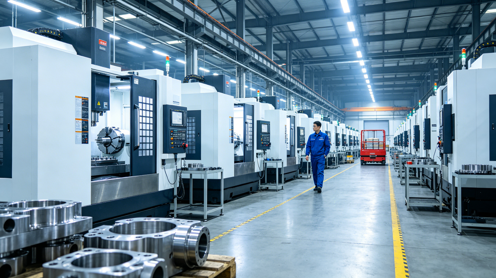
Not every curved contour demands 5‑axis capability; shallow open curved profiles with no hidden undercuts and accessible from top‑down directions can obtain acceptable outcomes from optimized3‑axis CNC milling operations. Shops can deploy ball‑end cutters with layered step‑down toolpaths to generate 3D curved shapes, though surface finish highly depends on step‑over distance and cutter deflection status. Parts with curved outer profiles yet all critical features exposed in one primary orientation avoid frequent re‑fixturing, minimizing cumulative positioning error risks. Shallow, open‑access curved geometry without compound angles remains economically viable for well‑tuned 3‑axis milling workflows.
Curvature boundary judgment: Parts with single‑direction gentle curves and zero undercut features are primary candidates for 3‑axis milling processing.
Toolpath optimization requirement: Fine step‑over parameters must be configured inside CAM software to reduce visible scallops across curved surfaces.
Fixture risk control: Avoid multi‑sided curved features requiring more than two re‑clamping cycles to limit stack‑up tolerance drift.
Cost‑performance balance: 3‑axis milling presents lower hourly rates and simpler programming for qualified mildly curved workpieces.
💡 Open‑type gentle curved components do not automatically require higher‑priced 5‑axis milling resources.
What curved‑part conditions make 5‑axis milling non‑negotiable?
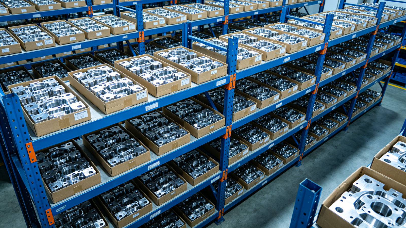
Once curved components contain compound multi‑directional curvature, deep enclosed cavities, internal undercuts or angled sculptured surfaces, standard 3‑axis milling workflows encounter insurmountable technical bottlenecks. Long overhang cutting tools become mandatory under 3‑axis constraints for deep curved pockets, generating obvious tool vibration, poor surface finish and elevated tool wear rates. Repeated re‑clamping for multi‑face curved features multiplies positioning deviation and expands inspection workload for high‑tolerance curved profiles. Continuously‑changing compound free‑form surfaces with hidden inaccessible zones can only achieve target quality with 5‑axis milling technology.
Compound free‑form surfaces: Organic continuously‑twisted curved shapes such as turbine blades and medical bone implants call for full simultaneous 5‑axis movement.
Deep enclosed curved cavities: Tilt‑capable tool orientation permits short rigid cutters to reach deep curved inner walls without excessive tool overhang.
Multi‑face curved feature sets: 5‑axis single‑setup processing eliminates stack‑up error caused by repeated fixture re‑positioning across distributed curved surfaces.
High‑end surface‑finish target: Dynamic tool inclination maintains ideal chip‑removal angle against curved profiles and reduces secondary manual polishing workload.
💡 Compound curvature, deep hidden cavities and multi‑face curved features represent core trigger conditions for selecting 5‑axis milling.
Performance comparison for curved‑part milling options
| Evaluation Item | 3‑axis Milling | Indexed 3+2 (5‑axis Positioning) | Simultaneous 5‑axis Milling |
|---|---|---|---|
| Applicable curved geometry | Shallow open single‑direction curves | Angled curved surfaces, non‑continuous contours | Organic compound free‑form curved surfaces |
| Required setups for multi‑face parts | 2‑6 times re‑clamping | 1‑setup indexing | 1‑setup full‑motion machining |
| Typical curved‑surface Ra value | 1.6‑3.2 μm | 0.8‑1.6 μm | 0.4‑0.8 μm |
| CAM programming complexity | Low | Medium | High, needs collision simulation |
| Relative production hourly cost | Baseline reference value | +30%~50% | +70%~120% |
Before finalizing your milling solution for curved workpieces, you can analyze your drawing geometry together with technical specialists contact us.
Practical workflow to decide milling axis for curved‑part projects
Designers and procurement engineers should follow a structured judging workflow rather than subjective preference when choosing milling axis for complex curved‑part projects. First analyze drawing geometry and confirm whether curved features belong to shallow open profiles or compound enclosed free‑form surfaces, and document tolerance requirements, target surface roughness and expected production batch volume. Then evaluate how many re‑clamping operations 3‑axis processing would demand and estimate cumulative positioning deviation risk for critical curved datums. Total end‑to‑end manufacturing cost including programming, fixture, rework and inspection must be calculated instead of only comparing machine hourly rates. After geometry‑based screening, you can select 3‑axis, indexed 3+2 or full simultaneous 5‑axis accordingly.
1.Geometry audit: Examine CAD drawing to categorize curved features as open shallow curves, angled discrete curved faces or continuous compound free‑form surfaces.
2.Tolerance & surface‑finish review: Confirm GD&T requirements and Ra targets for every critical curved profile of your component.
3.3‑axis feasibility assessment: Calculate re‑clamping count and judge whether accumulated positioning error will violate drawing tolerance specifications.
4.Cost‑driven final selection: Compare total project expenditure across feasible milling options and pick the scheme delivering optimal quality‑cost balance.
FAQ
Q1: What key performance benchmarks should I verify when sourcing curved‑part milling services?
A: You should confirm achievable profile tolerance for curved surfaces, guaranteed surface‑finish Ra range, simulation‑enabled CAM capacity and documented fixture‑error control protocol. Qualified vendors can hold curved‑profile tolerance within ±0.015 mm for 5‑axis work and provide pre‑production toolpath simulation reports for complex curved components, matching the quality expectation of aerospace, mold and medical‑device projects.
Q2: If I submit a curved‑part drawing for quotation, what documents and information do I need to provide for fast and accurate feedback?
A: You need to deliver native‑format 3D CAD files, 2D engineering drawings with complete GD&T annotations, expected batch quantity, material grade and key priority between cost, lead‑time and surface quality. Submit all materials via designated communication channel; reputable machining partners can complete technical evaluation within 12 working hours and return a formal quotation including recommended milling‑axis solution for your curved‑part project.
Q3: What are typical lead‑time and minimum‑order rules for 3‑axis and 5‑axis curved‑part milling?
A: For 3‑axis‑eligible curved‑parts, small‑batch prototyping supports MOQ 1 piece with standard turnaround of 5‑7 working days. Indexed 3+2 and simultaneous 5‑axis curved‑part prototyping normally requires 7‑12 working days; flexible production capacity can compress urgent prototype lead‑time down to 48 hours upon extra agreement. Batch‑order unit‑price discount applies when order quantity exceeds 20 pieces for multi‑axis curved components.
Q4: What countermeasures will suppliers take if delivered curved‑parts fail to meet geometry or surface‑finish specifications?
A: Formal quality inspection will be performed upon incoming goods; curved‑profile coordinate‑measuring‑machine scanning validates dimensional conformity. If non‑conformance is confirmed, vendors will clarify root causes such as tool‑deflection, fixture drift or toolpath defect. Acceptable parts rework will be arranged where geometry permits; otherwise free re‑manufacturing will be executed within agreed response time, and formal quality‑assurance records will be supplied for every order batch.
Q5: Can milling strategies be adjusted for my special curved‑part working conditions?
A: Process adjustments are feasible based on your service‑environment requirements such as high‑temperature operation, heavy‑load mechanical stress or strict anti‑corrosion needs. You need to provide detailed operating‑condition parameters and functional expectations for curved surfaces; process engineers will output adjusted toolpath, cutting‑parameter and tool‑material proposals within three working days. Customized process may raise unit‑part cost by 5%‑18% depending on modification scope.
Conclusion
Axis selection for complex curved milling projects should originate from workpiece geometry characteristics rather than pursuing higher‑spec machine capability blindly. Shallow open curved features can obtain satisfying results at lower cost from well‑optimized 3‑axis milling, while compound free‑form, deep‑cavity and multi‑face curved components demand indexed 3+2 or simultaneous 5‑axis milling to control positioning error and surface‑finish quality. Calculating full‑lifecycle manufacturing cost including programming, fixture and re‑inspection workload helps you avoid misleading comparisons based purely on machine hourly rates. Following structured geometry‑audit and feasibility‑assessment workflow allows manufacturing teams to strike stable balance between component performance, lead‑time and overall project budget.
For expert assistance in implementing milling strategies for your production needs, visit our resource center or contact us. Let’s help you scale up your manufacturing with precision and efficiency!