
Calculating optimal material thickness1 for load-bearing parts2 requires a systematic approach that balances structural requirements, weight constraints, and manufacturing feasibility – typically involving load analysis3, material selection4, and safety factor5 application to determine the most efficient cross-section. Through years of designing and manufacturing load-bearing components, we’ve developed a proven methodology that ensures reliability while avoiding unnecessary material usage.
The optimal thickness calculation process integrates engineering principles with practical manufacturing considerations, using formulas specific to loading types (bending, compression, torsion) while accounting for real-world factors like dynamic loads6, environmental conditions, and production constraints. This comprehensive approach moves beyond theoretical calculations to deliver practical, manufacturable solutions.
What Are the Fundamental Loading Considerations?
Understanding the type and magnitude of loads is the foundation of thickness calculation, with different formulas applying to tension, compression, bending, and torsion – each requiring specific analysis methods and safety considerations. Accurate load characterization is essential before beginning any thickness calculation.

Critical load considerations:
- Static vs dynamic loads: Impact forces require higher safety factors
- Load distribution: Concentrated vs distributed loads affect stress patterns
- Loading direction: Uniaxial, biaxial, or complex multi-directional loading
- Environmental factors: Temperature, corrosion, and vibration effects
- Service life requirements: Fatigue considerations for cyclic loading
Proper load analysis typically consumes 40-50% of the calculation effort but provides the essential foundation for accurate thickness determination.
How to Calculate Thickness for Different Loading Conditions?
Different loading conditions require specific calculation methodologies, with bending applications using beam formulas, compression7 members requiring buckling analysis, and torsion applications using circular section properties – each with unique governing equations. The calculation approach must match the primary loading mode.
| Loading Type | Primary Formula | Key Variables | Safety Considerations |
|---|---|---|---|
| Bending | σ = Mc/I | M=bending moment, c=distance, I=moment of inertia | Deflection limits, stress concentrations8 |
| Compression | Pcr = π²EI/(KL)² | E=modulus, I=moment, K=end condition, L=length | Buckling modes, end conditions |
| Tension | σ = P/A | P=load, A=cross-sectional area | Stress concentrations, connection design |
| Torsion | τ = Tc/J | T=torque, c=radius, J=polar moment | Warping, stress distribution |
These fundamental formulas provide the starting point for thickness calculations, which are then refined based on additional considerations.
What Safety Factors Should Be Applied?
Appropriate safety factors range from 1.5 for well-understood static loads to 4.0 or higher for dynamic, impact, or poorly characterized loading conditions, with selection based on material consistency, load certainty, and failure consequences. Safety factor selection significantly impacts the final thickness calculation.
Safety factor guidelines:
- Well-characterized static loads: 1.5-2.0 safety factor
- Dynamic or fatigue loads: 2.5-3.5 safety factor
- Impact or shock loading: 3.0-4.0+ safety factor
- Critical applications: Higher factors for life-safety components
- Prototype testing: Lower factors when validation testing is planned
Safety factors should be documented and justified as they represent the single largest variable in thickness calculation.
How Does Material Selection Impact Thickness Calculations?
Material properties dramatically affect thickness requirements, with high-strength materials allowing thinner sections but often introducing other considerations like brittleness, fatigue performance, or manufacturing challenges. Material selection and thickness calculation are interdependent decisions.
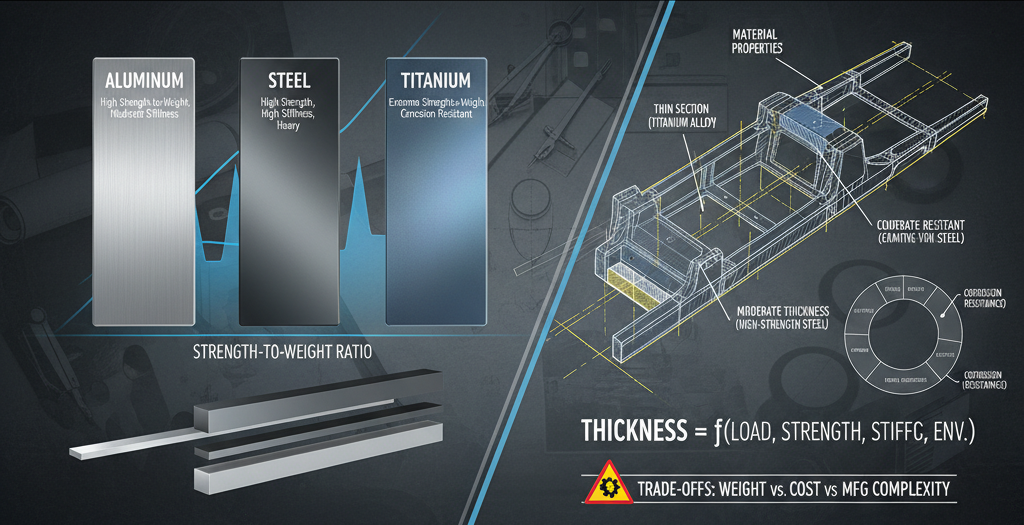
Material property considerations:
- Strength-to-weight ratio: Aluminum vs steel vs titanium comparisons
- Stiffness requirements: Modulus of elasticity effects on deflection
- Ductility needs: Material elongation for impact resistance
- Fatigue performance: Endurance limits for cyclic loading
- Corrosion resistance: Environmental considerations and allowances
Material selection often involves trade-offs between thickness, weight, cost, and manufacturing complexity that must be evaluated holistically.
What Manufacturing Constraints Affect Thickness Selection?
Manufacturing processes impose practical minimum thickness limits and affect material properties through factors like grain direction, residual stresses, and surface finish – all influencing the final thickness calculation. Manufacturing feasibility must be considered throughout the calculation process.
Manufacturing considerations:
- Process capabilities: Minimum thickness limits for each manufacturing method
- Material availability: Standard thicknesses and their cost implications
- Tooling limitations: Practical constraints on achievable dimensions
- Quality control: Measurement and tolerance capabilities
- Secondary processing: Effects of heat treatment, plating, or coating
These practical considerations often override theoretically optimal thicknesses, making early manufacturing involvement crucial.
What Software and Tools Support Thickness Calculations?
Modern thickness calculation utilizes FEA software, CAD integration9, and specialized calculation tools that automate complex analyses while providing visualization and optimization capabilities unavailable with manual methods. Appropriate tool selection enhances calculation accuracy and efficiency.
Calculation tools and methods:
- Finite Element Analysis (FEA)10: For complex geometries and loading
- CAD-integrated analysis: Direct analysis within design environment
- Spreadsheet calculators: For routine, standardized calculations
- Industry-specific software: Tailored to particular applications
- Prototype validation: Physical testing to confirm calculations
The most effective approach typically combines multiple tools, with FEA for complex areas and manual calculations for verification.
How to Validate and Verify Thickness Calculations?
Calculation validation involves cross-verification using multiple methods, comparison to similar successful designs, and ultimately physical testing to confirm performance under actual loading conditions. Validation ensures calculations translate to reliable real-world performance.
Validation methodology:
- Multiple calculation methods: Independent verification using different approaches
- Similar part analysis: Comparison to proven designs in similar applications
- Prototype testing: Physical testing under simulated service conditions
- Progressive refinement: Iterative improvement based on test results
- Documentation review: Peer review of calculations and assumptions
This comprehensive validation approach typically identifies 15-25% of calculations requiring refinement before finalizing thickness decisions.
Ready to Calculate Optimal Thickness for Your Load-Bearing Parts?
Our engineering team combines analytical expertise with practical manufacturing knowledge to calculate optimal material thickness for your specific application, ensuring reliable performance while minimizing weight and cost. Contact us for a comprehensive thickness analysis and manufacturing assessment.
Why manufacturers trust our calculation services:
- Advanced FEA and simulation capabilities
- Multi-material expertise across metals and composites
- Manufacturing process integration
- Prototype testing and validation
- Industry-specific experience and standards knowledge
Don’t rely on guesswork for critical load-bearing components – leverage our expertise to calculate the optimal thickness for your specific application requirements.
-
Calculating material thickness is essential for ensuring structural integrity and performance in engineering. ↩
-
Understanding load-bearing parts is crucial for effective design and safety in engineering applications. ↩
-
Load analysis is fundamental for determining the safety and reliability of structures under various loads. ↩
-
Material selection impacts performance, weight, and cost, making it a critical decision in engineering. ↩
-
Safety factors are critical for ensuring that structures can withstand unexpected loads and conditions. ↩
-
Understanding dynamic loads helps in designing structures that can handle varying forces over time. ↩
-
Compression is a vital loading condition that influences the design and durability of structures. ↩
-
Understanding stress concentrations is crucial for preventing failures in load-bearing components. ↩
-
CAD integration enhances accuracy and efficiency in the design and analysis process. ↩
-
FEA is a powerful tool for analyzing complex structures and optimizing designs. ↩